| Mark-8 Design | Microcomputer According to Titus | Microcontroller Project | Postscriptum | Lessons Home |
Lesson 4: Digital Circuits
The Pico is a simplistic piece of electronics. This board is designed for easy assembly and therefore the processor has a more direct influence on the execution of the system. Everything in the system is connected directly to the processor, by changing the bits of the processor the system will change in response. This section will show you how the important parts of the Pico are all connected into the SX-28 processor.
Contents [hide]
SX-28 processor Diagram
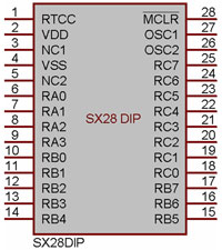
Figure 4-1: SX28 Processor diagram
| Pin # | Representation | Description |
| 1 | RTCC | Input to realtime clock/counter |
| 2 | VDD | Positve Supply Pins |
| 3 | NC1 | Ignored on the XGameStation Pico |
| 4 | VSS | Ground |
| 5 | NC2 | Ignored on the XGameStation Pico |
| 6-9 | RA0-RA3 | Control LED’s |
| 10-17 | RB0-RB7 | Control Input Pins |
| 18-25 | RC0-RC7 | Control Video/Audio Output Pins |
| 26-27 | OSC2-OSC1 | Oscelator input/output |
| 28 | MCLR | Master clear reset input |
Pico Input Devices
The input devices are used to send data into the Pico where it shall then be processed by the processor and determined how to act based on the code. The primary input device for the Pico is a 7-pin ATARI Joystick. The following chart explains how the pin number relates to the wire colors of the joystick.
| Pin # | Color | Function |
| 1 | White | Up |
| 2 | Blue | Down |
| 3 | Green | Left |
| 4 | Brown | Right |
| 5 | - | - |
| 6 | Orange | Fire |
| 7 | - | - |
| 8 | Black | Ground |
| 9 | - | - |
The following diagram shows how the joystick is connected to the processor. Each RB register connects to a unique pin of the joystick port.
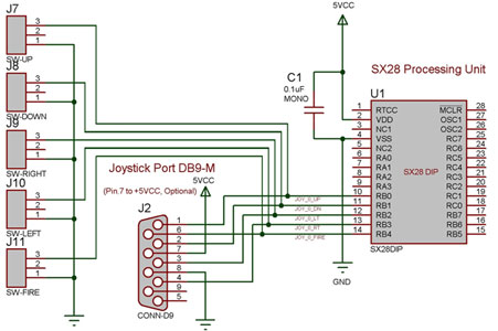
Figure 4-2: Joystick/Button Diagram
Pico Output Devices
Pico output circuitry is very simple, it is all done over the RC register. Since the hardware is so simple much work must be done in the code. The audio and video circuits are very similar, they are almost identical except for the fact that they connect to the opposite halves of the RC register. The audio portion takes the upper RC and the video takes the lower RC.
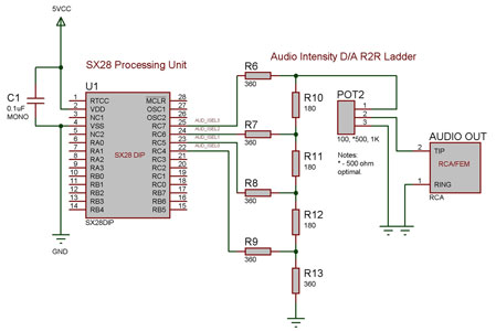
Figure 4-3: Audio Circuit Diagram
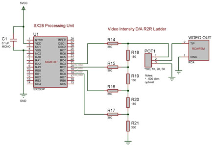
Figure 4-4: Video Circuit Diagram
The LED’s are another form of output that provide a simplisitc way of displaying data without dealing with the RC register. The RA register is used to control each one of the four LED’s. The use is quite simple by just setting the certain RA bit you can turn on/off the corresponding LED.
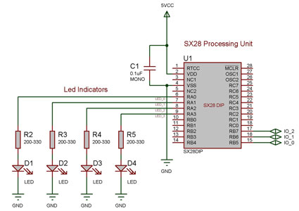
Figure 4-5: LED Circuit Diagram
Clock Diagram
The SX 28 internal oscillator Is not that fast so an external oscillator can be hooked up to the processor as shown in the diagram to increase the operation cycles per second.
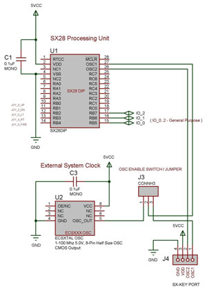
Figure 4-6: Clock Circuit Diagram