| Mark-8 Design | Microcomputer According to Titus | Microcontroller Project | Postscriptum | Lessons Home |
Lesson 11: Pico Advanced Topics
This module will cover ideas for usage of the expansion port located on the XGS Pico 2.0 system. All of the pins of the SX-28 processor that the expansion port connects to are fully configurable for either input or output so you basically have 12 pins to work with. We will cover some basic ideas, but the sky is really the limit.
Contents [hide]
Pico Expansion Port
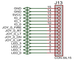
The Pico 2.0 contains an expansion port that can be used to access the RA and RB pins of the SX-28. Additional I/O devices may be connected to the expansion port and be used instead of the LED array and on-board buttons.
 |
||
| Pin # | Function | SX-28 Pin |
| 1 | LED_0 | RA.0 |
| 2 | LED_1 | RA.1 |
| 3 | LED_2 | RA.2 |
| 4 | LED_3 | RA.3 |
| 5 | JOY_0_UP | RB.0 |
| 6 | JOY_0_DOWN | RB.1 |
| 7 | JOY_0_LEFT | RB.2 |
| 8 | JOY_0_RIGHT | RB.3 |
| 9 | JOY_0_FIRE | RB.4 |
| 10 | IO_0 | RB.5 |
| 11 | IO_1 | RB.6 |
| 12 | IO_2 | RB.7 |
| 13 | 5VCC | - |
| 14 | GND | - |
| 15 | GND | - |
Input Devices
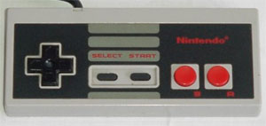
A popular input device that is often used with Pico systems is the standard NES controller. The NES controller has 8 buttons: up, down, left, right, a, b, start, and select. To get the NES controller working with the XGS Pico would be a great small project as how it would interface with the system is completely different than the ATARI joystick. The ATARI joystick has one pin corresponding to each button making it very simple to check for whether a button has been pressed whereas the NES controller only has one pin for data output.
Output Devices
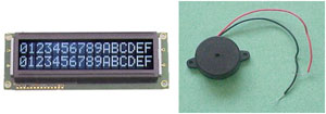
An LCD screen would be a nice addition to the Pico. I found that synchronizing the code to output to the NTSC television standard was a bit unwieldy and outputting to an LCD remedy this. If a small LCD screen were to be added to the Pico it could be fashioned into a simple calculator or clock. Another interesting path to take would be to connect a buzzer to promote on-board sound capabilities.