|
In the '60's and '70's, electronic experimenters often used a piece of Veroboard or "strip board" to build prototypes or one-off circuits. Vero Technologies, Ltd. manufactured (and still manufactures) a variety of different board sizes that experimenters use as is or that they cut to shape. To understand how to use Veroboard, imagine an array of small holes drilled in a 0.1-inch by 0.1-inch pattern through circuit-board phenolic material. Then imagine that a copper strip on one side of the board connects all the holes in one horizontal row. These copper strips provide conductors. To build the Mark-8, I used two pieces of Veroboard that measured about 5 inches by 8 inches. The copper strips ran parallel to the long dimension. Vero provided a small hand tool that had a conical point, much like the point of a drill. By placing the tool's point in a hole of the conductor side of the board and turning the tool back and forth, I removed copper and isolated sections that became short conductors. Here's a photo that shows how the tool would remove copper: 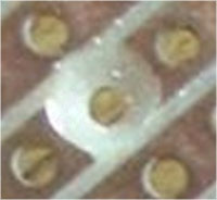 Photo courtesy of Mike Gordon. Hobbyists had to use the tool carefully so they did not leave "cat's whiskers" of copper connected to the cut traces. They also had to cut far enough to completely break the copper conductor and also not cut into the adjacent conductors. You can learn more about Veroboard preparation at: www.smspower.org/smsreader/prepare.html By carefully planning the placement of components, I made the two pieces of Veroboard accept 14-pin and 16-pin ICs in dual in-line packages (DIPs). Because the uncut strips ran the length of each board, I used strips between ICs to provide power and a return ground path. You can see this in the diagram below. 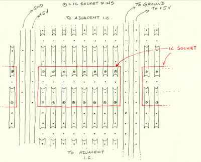
Cutting 16 "holes" by hand for EACH integrated-circuit socket would produce a lot of hand fatigue and calluses. So, instead of using the hand tool, I put an equivalent-size drill bit in my small Unimat lathe/milling tool that I set up as a drill press. I limited the depth of the cut so that each drilling action created a perfect cut of the copper runs on the Veroboard material. Here is an example of the type of Unimat I used--and still have: 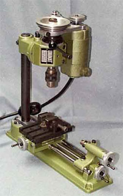 Unimat photo courtesy of Steve Jaynes. The resulting pattern provided two possible solder connections for each IC pin. Because the 8008 socket required 18 pins, I expended the column for the 8008 chip to accommodate 18-pin sockets. All the other rows could accept 16-pin sockets. Instead of using plastic IC sockets, which cost quite a bit, I used "socket strips" from Molex. These strips provided a continuous row of IC socket pins with a piece of break-away metal that connected them. I cut strips into 7-pin, 8-pin, and 9-pin lengths, soldered them in place, and broke off the connecting strip of metal. Instant IC socket pins all nicely aligned in a row. This type of "socket" provided no insulation between pins, though, so I had to ensure that during assembly of each board I did not push the pins together or let wires push them together to create short circuits. Although not the type of pin I used, the photo below shows the technique. Imaging a solder-pin on the free end (bottom) of each pin and you will get the idea. 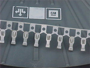 Courtesy of Digital Design, Bemidji, MN. As best I can tell, Molex no longer manufactures the type of "socket strip" I used to construct the Mark-8 prototype. The final Mark-8 design also used the "socket-strip" contacts in place of plastic IC sockets because hobbyists had to solder circuit-board traces on both sides of each board. |